
If you access the help [http://help.scilab.org/docs/5.5.2/en_US/PID.html] for the PID block you get this diagram
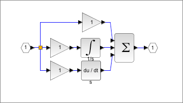
which shows that the PID block is a simple function consisting of the three separate calculations configured in a non-interacting way.
If you dig around in the help you will find the PID equation that is being implemented;
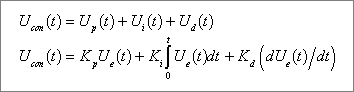
which confirms this.
But what do each of the three tuning terms do? Well the help sort of explains but I always like to check so I built the following in XCos and then did some tests.
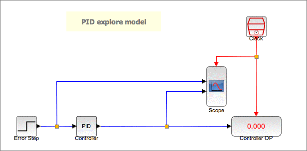

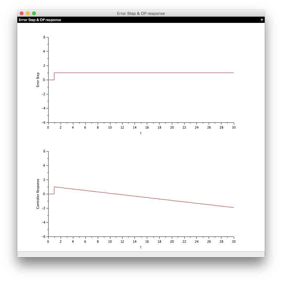
The PID block needs an error input which it will try to drive to 0 via its algorithm and the tuning applied.
The above injects a +1 step into the PID block. This represents an error step of +1. The model trends this input value and the output value of the PID block. The output value of the PID is also shown.
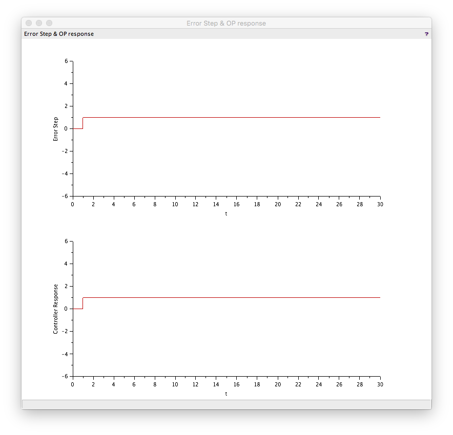
Test results
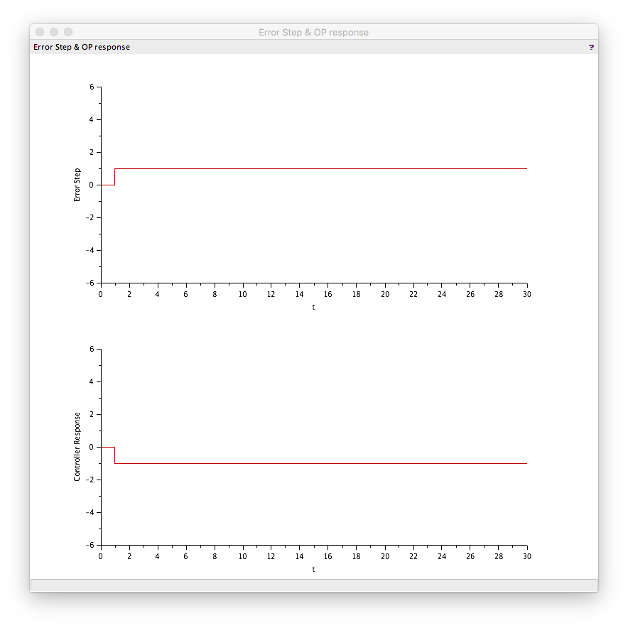
Test 1: K=1, other terms 0
This yielded a final output of 1 with the following profile. This is typical of a pure gain controller so the P term is actually pure gain.
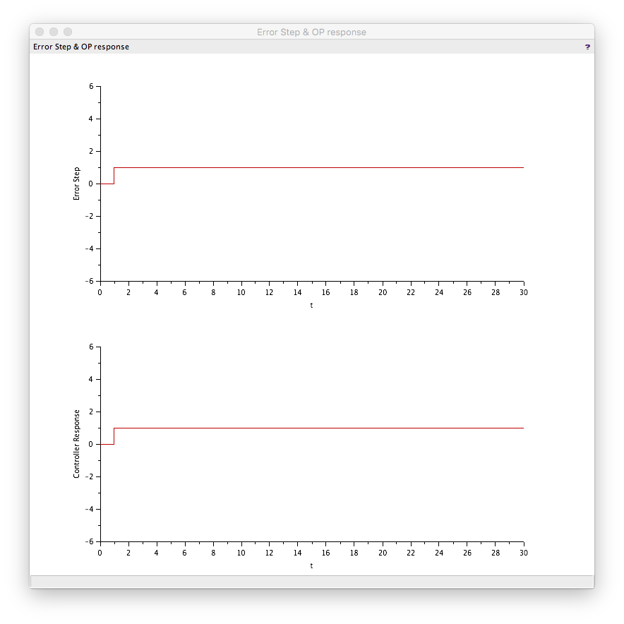
Test 2: K=-1, other terms 0
The opposite of test 1. So to get an inverse acting controller you set K equal to a negative value.
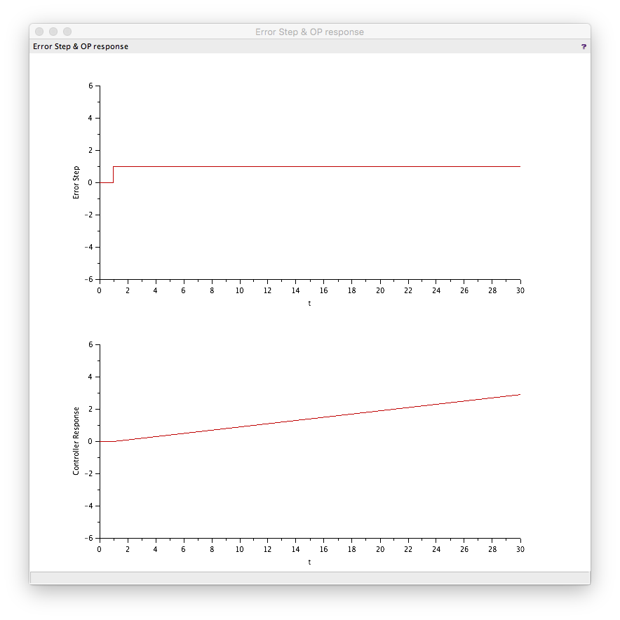
Test 3: I=0.1, other terms 0
Here the final output is 2.9 because the is 1x0.1 for 29 cycles which if integrated gives 2.9.
Test 4: D=1, other terms 0
Big kick in output for the error step but no return as expected. The first time I did this I got a derivative kick as expected but on all subsequent occasions I got a step change similar to the pure gain configuration. I still don't know why!
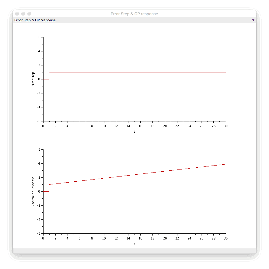
Test 5: P=1, I=0.1, D=0
Gave the combination of test 1 and test 3 as expected. The output shows the P kick when the error occurs and then the integral action builds the controller output over the test time.
Test 6: P=1, I=-0.1, D=0
So we have a positive gain and a negative integral time! I have not seen this ability in an off-the shelf algorithm on an industrial control device but XCos lets you do and it gives you the expected result i.e. test 1 minus test 3.
Conclusion
The build-in PID block is a very basic PID block that is easily understood but very different from that available on industrial control devices. It is a non-interacting type and uses pure gain, integral factor per scan and a pure derivative multiplier.
It lacks many of the “standard” features of an industrial controller implementation;
- integral wind-up protection
- saturation limits
- algorithm type selection
- mode switching
but these functions can be easily added using the other blocks available.
The derivative function does not seem to be working as expected but fortunately this is rarely used. A colleague often states that the "D" in "PID" stands for "don't use!".
However, even in its “raw” form it functions as a real controller: attempting to drive error to 0, and so can be used to test control strategies if accurate modelling of the response is not required.
More
For more information on the PID block within Xcos see;